Temporary Microgrid Design and Test Procedures
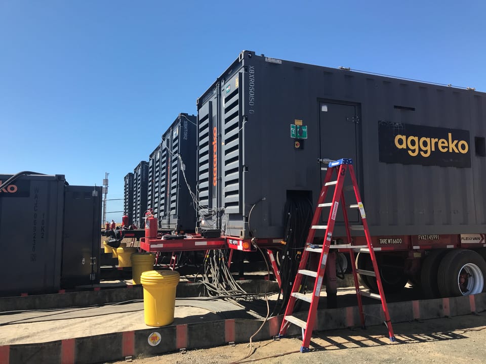
This post details the engineering procedure of designing, developing a test program, and commissioning a temporary, 12kV-connected microgrid to support transmission work or a substation replacement.
The necessity of the a temporary microgrid comes from maintenance or emergencies in the electric grid system that renders a substation unable to provide power to the area. This could be due to transmission line work on a sparsely-connected grid system or due to emergency failure of substation equipment.
The project has a few main steps
- Look for alternative solutions to temporary generators– can the load be supported by other distribution backties in the area? What if we just did the work during the night during low loads? Many times it is historical evidence that provides the justification – "we tried to offload the substation to the local network but we received many voltage complaints from customers". The power flow simulation software can only do so much and power engineers should lean on the side of safety and avoid pushing the system to its limits, especially for untried situations.
- Feeder load calculations for the substation offload – to determine the amount of generation we need to procure, we look at historical loads for the area around this same season and take into account any system abnormalities, weather, or other reasons that the load might be different in the future. We also take into account minimum load requirements, reactive power flow, and the three-phase load balance of the system.
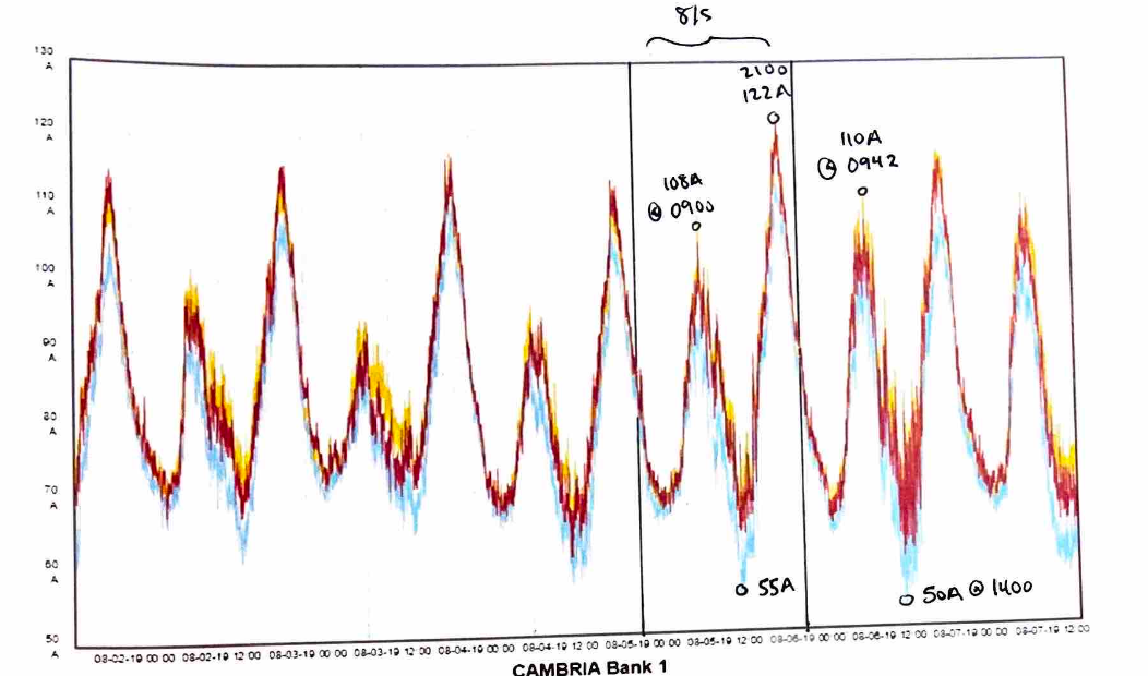
The generators also need a minimum amount of load to prevent "wetstacking". For example, the total minimum load should be greater than 30% of the total rated nameplate.
Also further de-rating of the generator is required if a majority of the load is single phase, which often happens in the same areas that have weak backties and require this type of work.
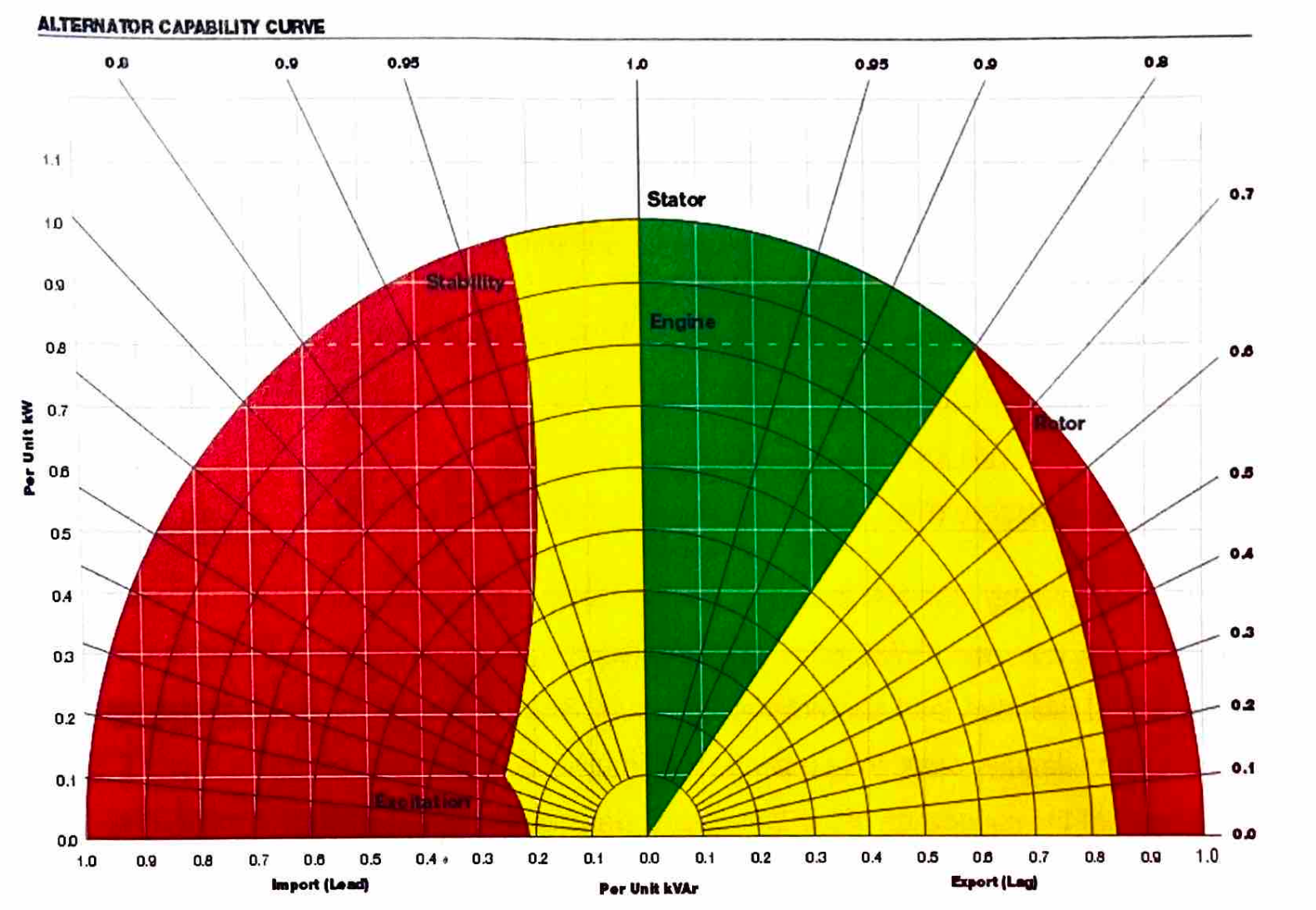
In addition to current, we must also take into account the power factor and VARs on the system. Typically diesel generators don't run too well supplying power to capacitive loads (leading power factor) and a "maximum reverse kVAR" will be supplied by the manufacturer.
- Fault calculations and revised system settings – since we will be disconnected from the transmission system, our fault duty will be reduced. We have to look at the data sheet of the generators and see how much fault current they will contribute to a bolted fault. We model this in our power flow simulation software to see what the minimum fault current seen down the line and have to check that our protective equipment will trip for this amount of current.
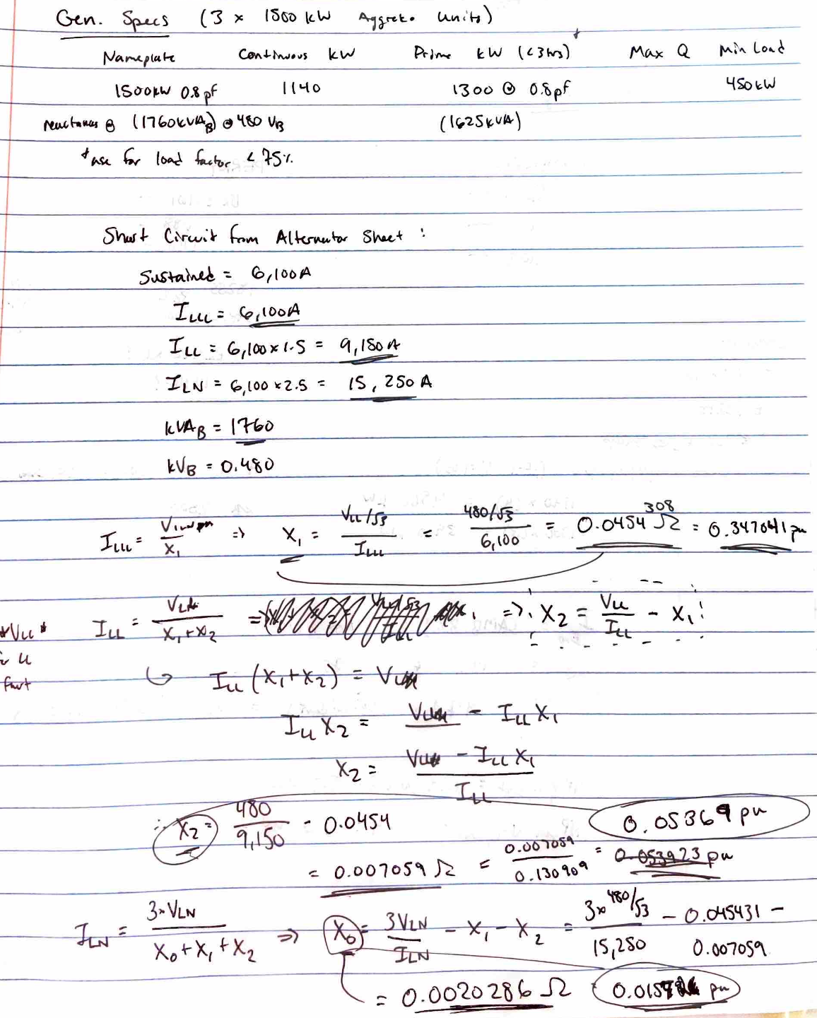
Generator specs: The generator used was a 480V 4-pole 60 Hz generator is powered by a Cummins diesel prime mover. The three-phase synchronous generator has a separately excited permanent magnetic generator for field excitation. The generator is stepped up to the distribution "primary" voltage by appropriate step up transformers.
- Single Line Diagram creation – Once the number and size of generators is chosen, a schematic is created to show the connection to the existing system
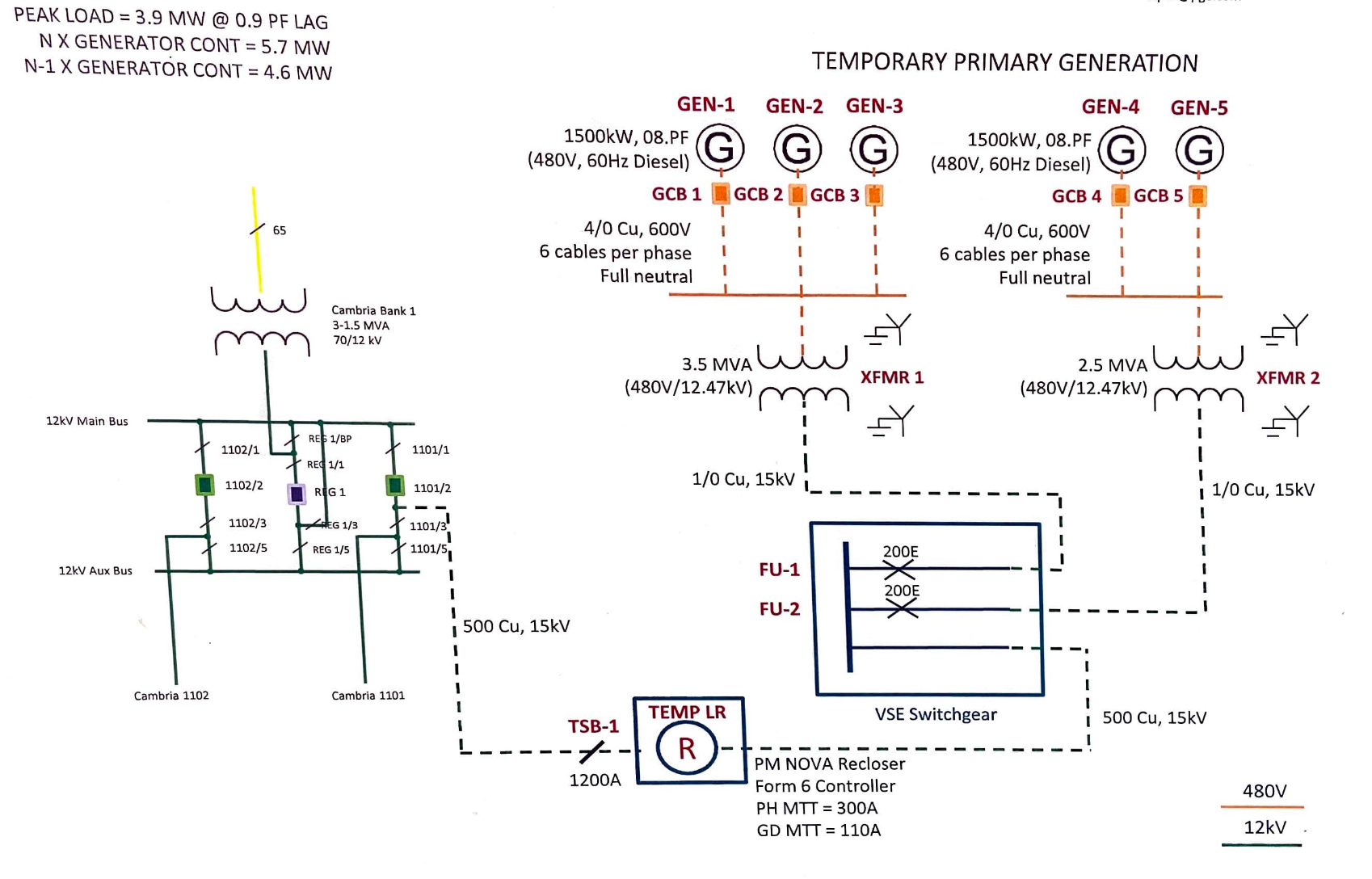
- Test Program – one of the most critical points is writing a test program for the operators to execute that makes sure the temporary generator(s) are safely connected and disconnected from the grid. This involves detailed steps on open/close/test operations for the field personnel. The test program will depend on whether the generators are synchronizing into the existing distribution system or supplying an islanded system.
- Construction – construction should be verified to align with the schematic. An important consideration is the grounding scheme, since many times there may not be a substation grounding grid to tie into, and a new multi-point grounding grid should be created that can handle the fault duty. Soil tests should be performed to make sure the resistance is adequately low enough to provide a good fault path.
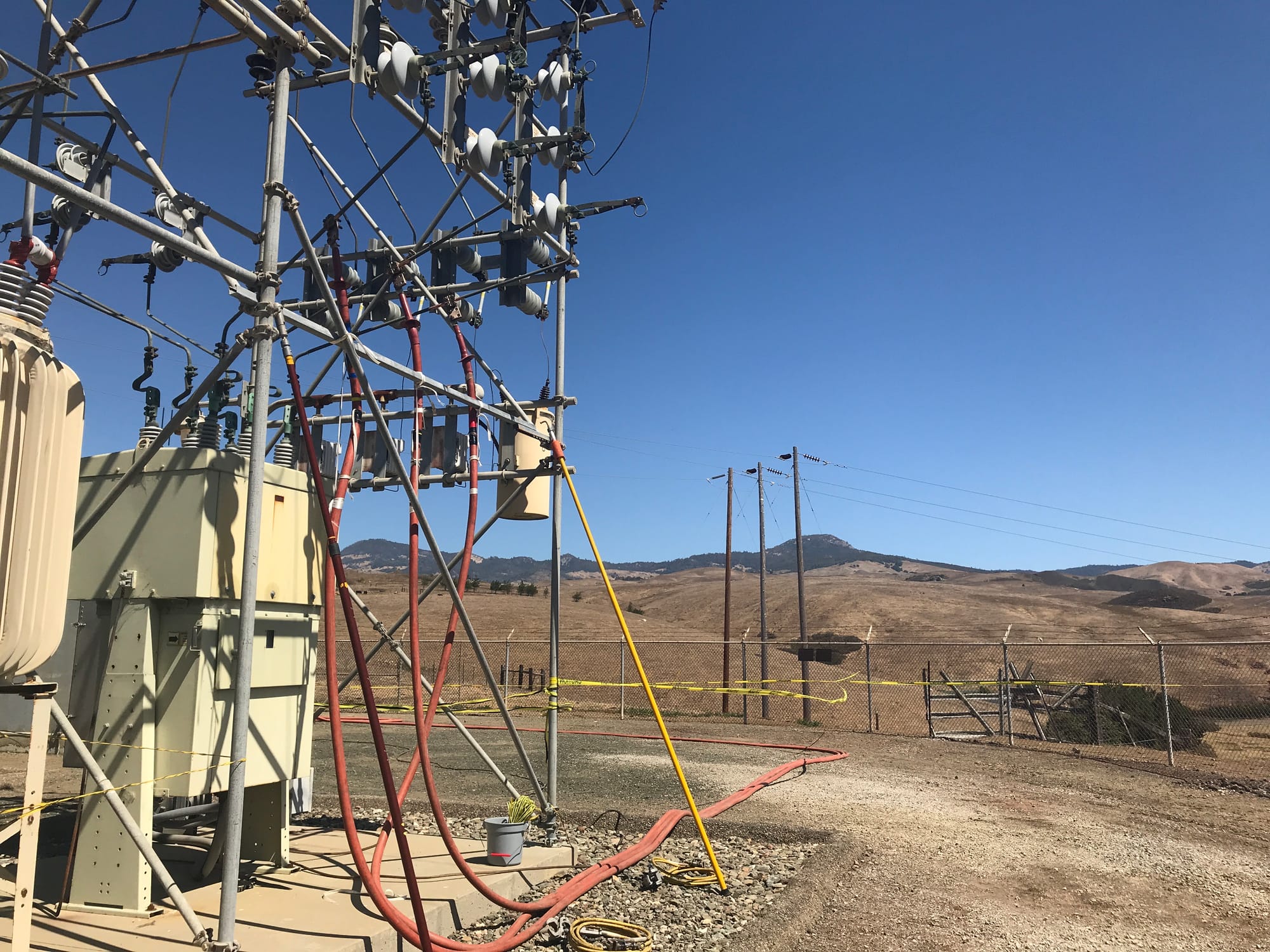
- Commissioning and Operations - once the site is constructed and the test program is approved, ideally the engineer who designed the program will be on-site for the commissioning. I was lucky enough to have this opportunity a few times, and typically I would monitor the loads and voltages to make sure they were in line with what I had calculated for that hour of the day. It's a good idea to check the loads and voltages during peak to make sure the voltage regulator on the generator is working properly.