[Active] Seven Segment Display Driver
![[Active] Seven Segment Display Driver](/content/images/size/w960/2024/05/sev-seg-block-diagram-1.png)
Posts in this series: Phase 1 – Architecture Overview and Hardware Prototyping
Overview:
An extensible hardware and software solution for driving a wall of seven segment displays. A "display module" will consist of multiple LED driver chips each driving a maximum number of digits, commanded by a single STM32 driver MCU. A master controller decodes animated gifs and sends a serial byte command of SPI to the display modules, then sends a synchronized update command. Per-segment brightness control will be implemented in version 2.
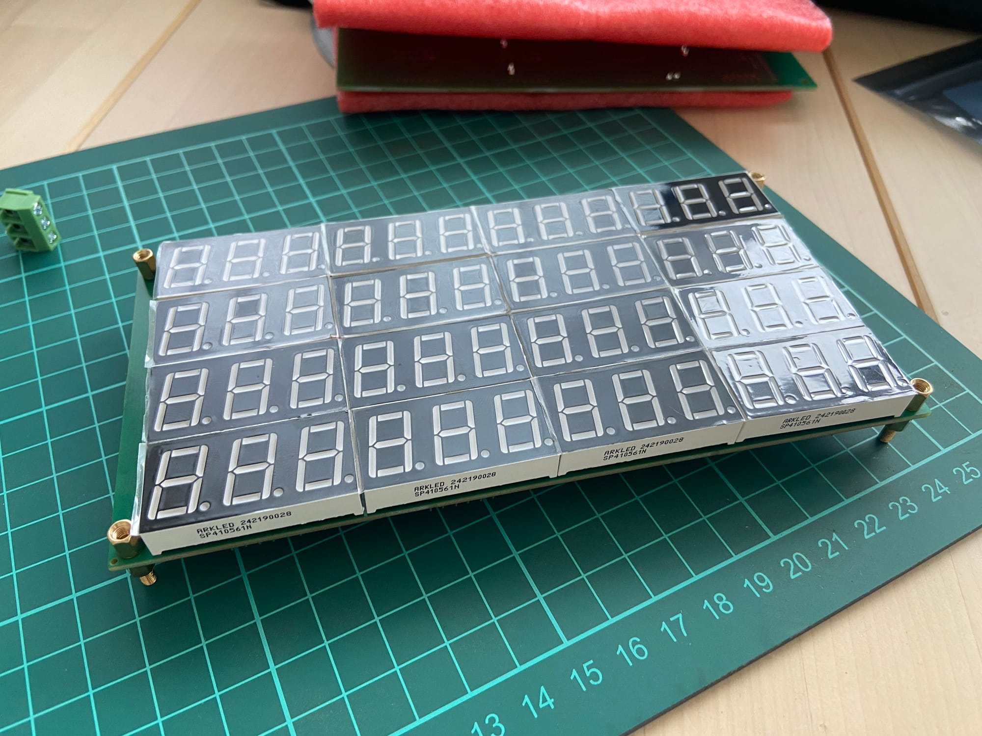
Goals:
- lowest possible cost – a preliminary calculation is at $0.20/digit, so for a 36x36 digit display around $260
- module-based – user can string modules together to drive bigger and bigger display walls
- (stretch/v2) individual segment-level control — see why this is a v2 goal below (depends on driver chip)
- (stretch/v2) integrates with current libraries like SmartLED/FastLED
Links and Supporting Posts:
See supporting blog posts and links below. You can always drop me a line if you have comments, advice or want to collaborate.
- Detailed post on Tm1637 library and logic analyzer captures (In Progress)
- General post on multiplexing architectures (In Progress)
System Architecture
The system consists of
- Manager: The main controller that packages and sends the serial bit stream for each display frame.
- Shift Register(s): as a GPIO expander for the SPI CS pin for the modules. These aren't needed if we can daisy-chain modules together (see §Scope Creep below).
- Modules: Each has a single STM32 MCU that drives (4) x LED Drivers (TM1637). A level shifter may be included. Since each driver can drive 6 digits each module command 24 digits.
- Seven-Segment Driver chip: The TM1637 driver chip can drive up to 6 digits and is commanded by a max 250kbps I2C-esque serial signal from the MCU. A library for STM32 is readily available.
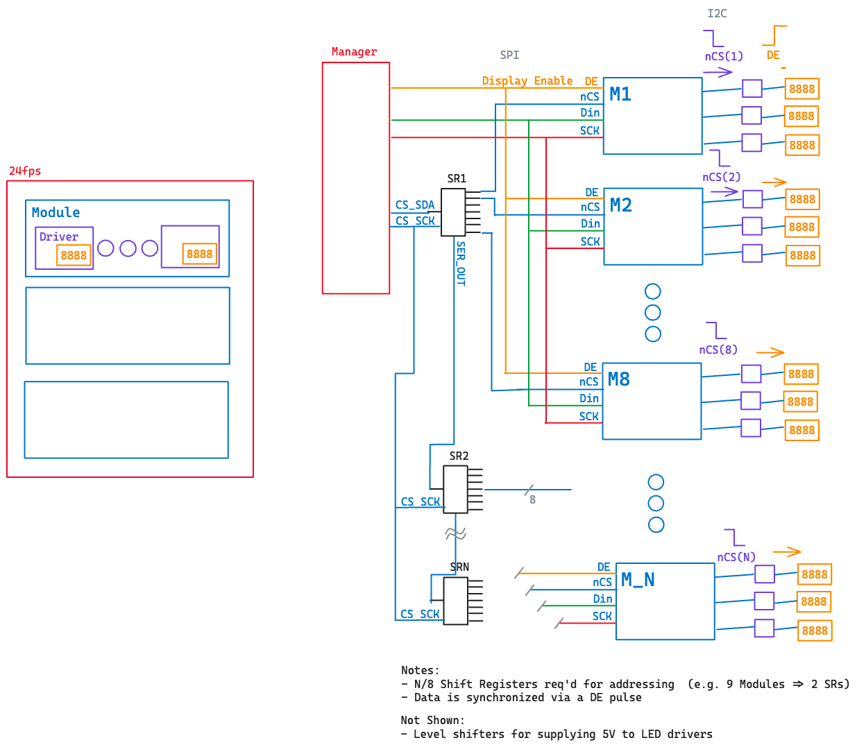
Each STM32-based module will then send out four interleaved I2C-like signals to the TM1637 display driver chips. Since each driver chip drives 6 digits each we will update all 6 digits, giving a digit refresh rate of ~290us for a 250kbps serial clock. The TM1637 modules then continuously multiplex/refresh the displays with this given data without further commands.
Since all of the driver chips are commanded at about the same time (the STM32 can easily interleave 3 bit-banged 250kbps Clock and Data lines) we should have a synchronized update across all digits.
The timing requirements are calculated based on a 24Hz refresh rate for the whole frame, giving for example a required processing period of a module of 2ms for a 24Hz refresh rate.
1/24Hz ~= 42ms → 42ms/20modules ~= 2ms/module.
Each module must take in the SPI data, update its internal memory mapped registers that hold the status of the display segments (or an internal array), and then wait for the command to send the data out to the TM1637 driver. In reality below only during the last module period will this command be sent since only at this time will all of the modules have their data.
Note that the limiting factor is how fast the TM1637 serial clock runs that updates the individual digits, which in this case with some buffer time is calculated around 288us for updating all 6 digits at 250kbps.[[1]]
Future / Scope Creep
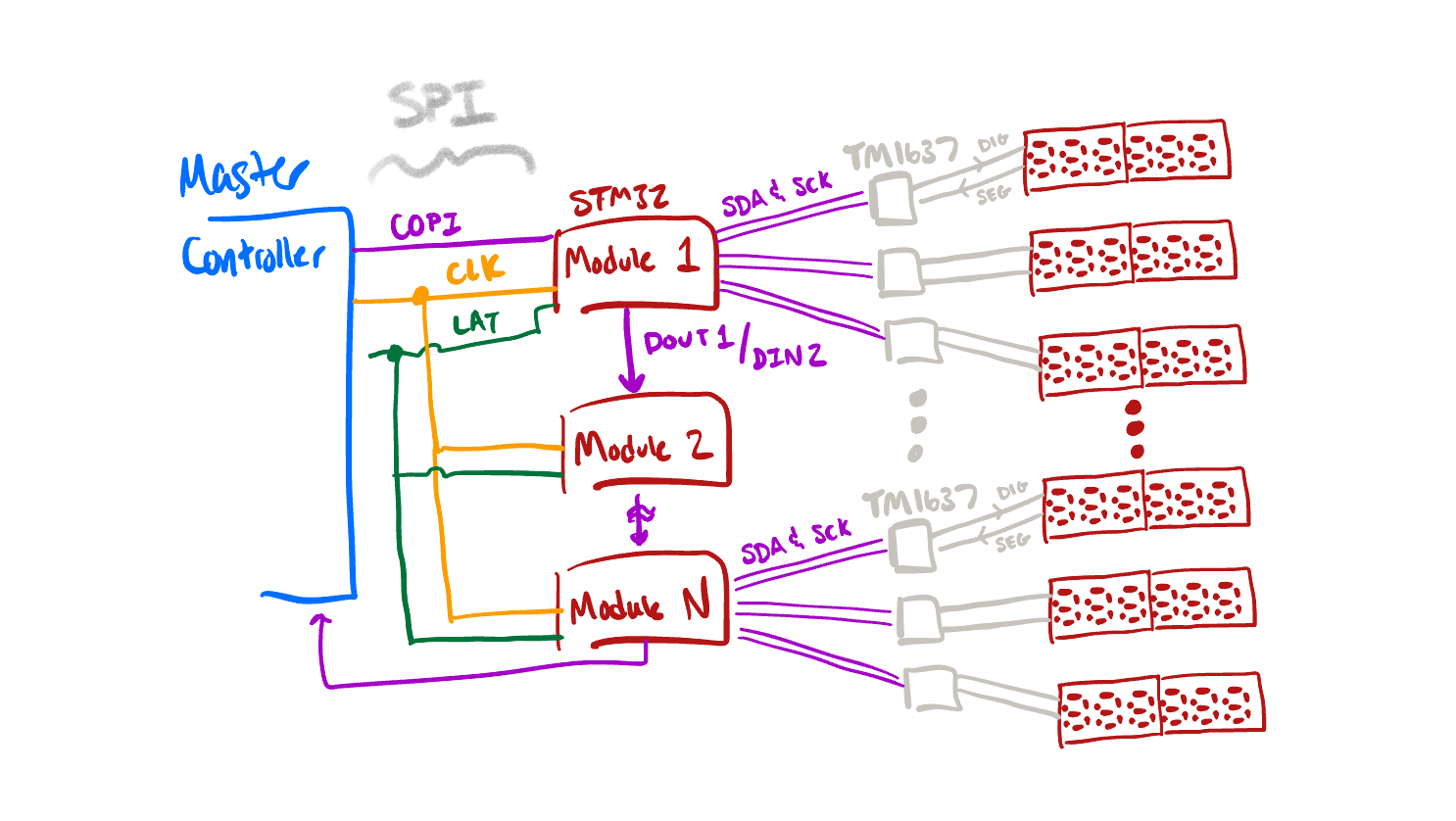
Daisy chaining SPI (🔧)
The daisy-chained SPI configuration is on hold until I get further into the firmware capabilities of the STM32C0 series chip. Apparently implementing a full-duplex SPI peripheral is not trivial (issues with the SPI peripheral timing using a shared Tx/Rx buffer), although if the delays are deterministic and accounted for it shouldn't matter if it isn't truly fully duplex as long as the time delays aren't so large that they affect larger displays.

Inspired By
[[1]]: Note that the limiting factor is how fast the TM1637 serial clock runs that updates the individual digits, which in this case with some buffer time is calculated around 288us for updating all 6 digits at 250kbps.
